Tutorial - Process Model
Until now, we can model a lot of features of our website. But we have never talked about how the actions of our process classes look like. The Process Model comprises:
- the Process Structure Model describing the relations between the different process classes, and
- the Process Flow Model specifying the activities connected with each «processClass».
Process Structure Model
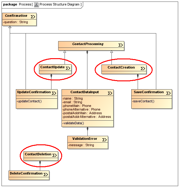
In order to describe the relations between the different process classes, we create a Class Diagram, using the Navigation to Process Structure Transformation. After this we have a class diagram with the three red-bordered classes on it:

As you can see, we added other classes to express, that all three operations include a Confirmation (remember our Presentation Diagram) with a question. This means that if the user wants to delete a contact, a Message will be shown and after clicking ok, the contact will be deleted. ContactCreation and ContactUpdate are working very similar, both inherit the abstract class ContactProcessing, assuring that the text fields, which are attributes of ContactDataInput, contain valid values (e.g. we can think about prohibiting an empty name to avoid useless entries in the database). If it is possible to validate the user data, no ValidationError occurs and the Confirmation page is shown. But for the details of the activities, look at the next paragraph!
Process Flow Model
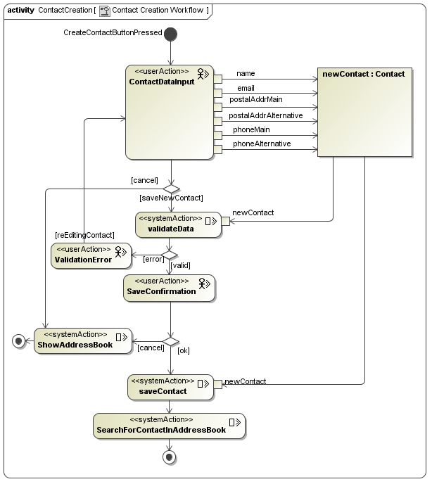
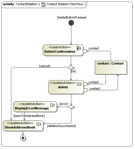
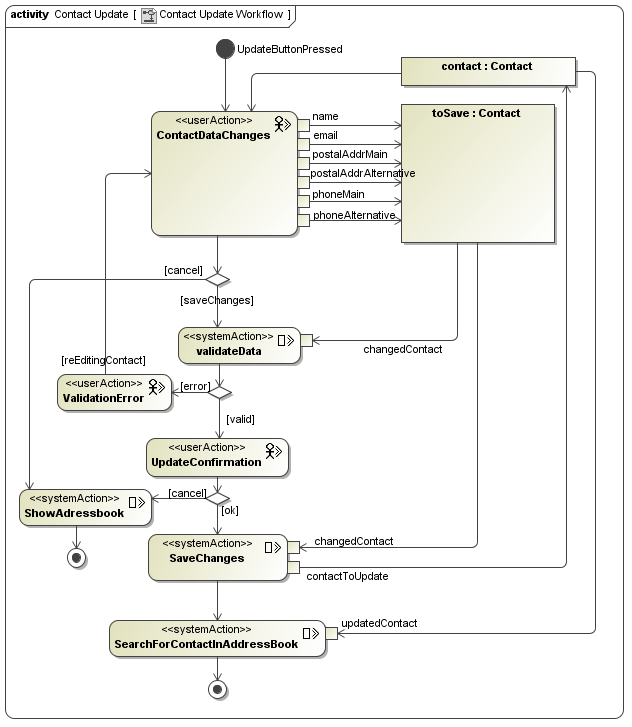
A Process Flow (or Workflow) is an Activity Diagram, describing the behaviour of a ProcessClass, e.g. what will happen in detail, if the user navigates to a ProcessClass (like ContactCreation in our example).
| stereotype-names and their icons | |
|---|---|
 userAction userAction |
 systemAction systemAction |
We can select our Navigation Diagram and run the Navigation to Process Flows Transformation. Now we have three empty activity diagrams:
- ContactCreation
- ContactDeletion
- ContactUpdate
The «user Action» stereotype is used to indicate user interactions on the web page initiating a process or responding to an explicit requirement of information. By contrast, «system Action» describes actions, which are executed by the system. Both types of actions can be inserted using the toolbar.
Congratulations! :-)
This is the end of this UWE tutorial, because you need only standard-UML to express what happens in these three Process Flow Diagrams.


Have also a look at the models from the example section.


